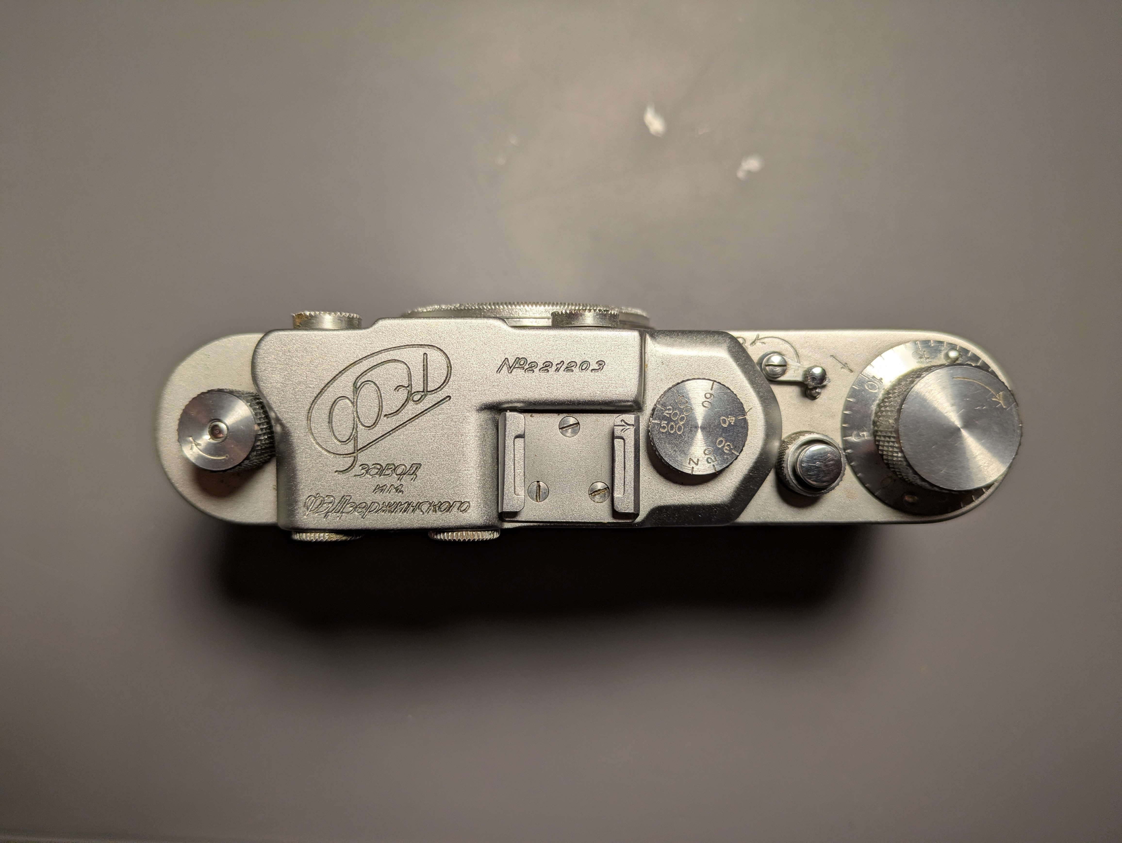
FED 1 - No. 221203
I'll be using these pages to document a rebuild I'm trying on a FED 1 camera I recently purchased on ebay (before the tariffs!). I have bought a few FED 1s and 2s, as well as a few lenses, from Ukraine (Слава Україні!). I picked this one - No. 221203 - as a good candidate for a rebuild as it seemed to be in decent condition. The shutter is cracked and flaking, and winding is stiff, but it looks clean and there seems to be little to no signs of damage to screw heads, etc. from previous repair attempts. We'll see as we get into it!
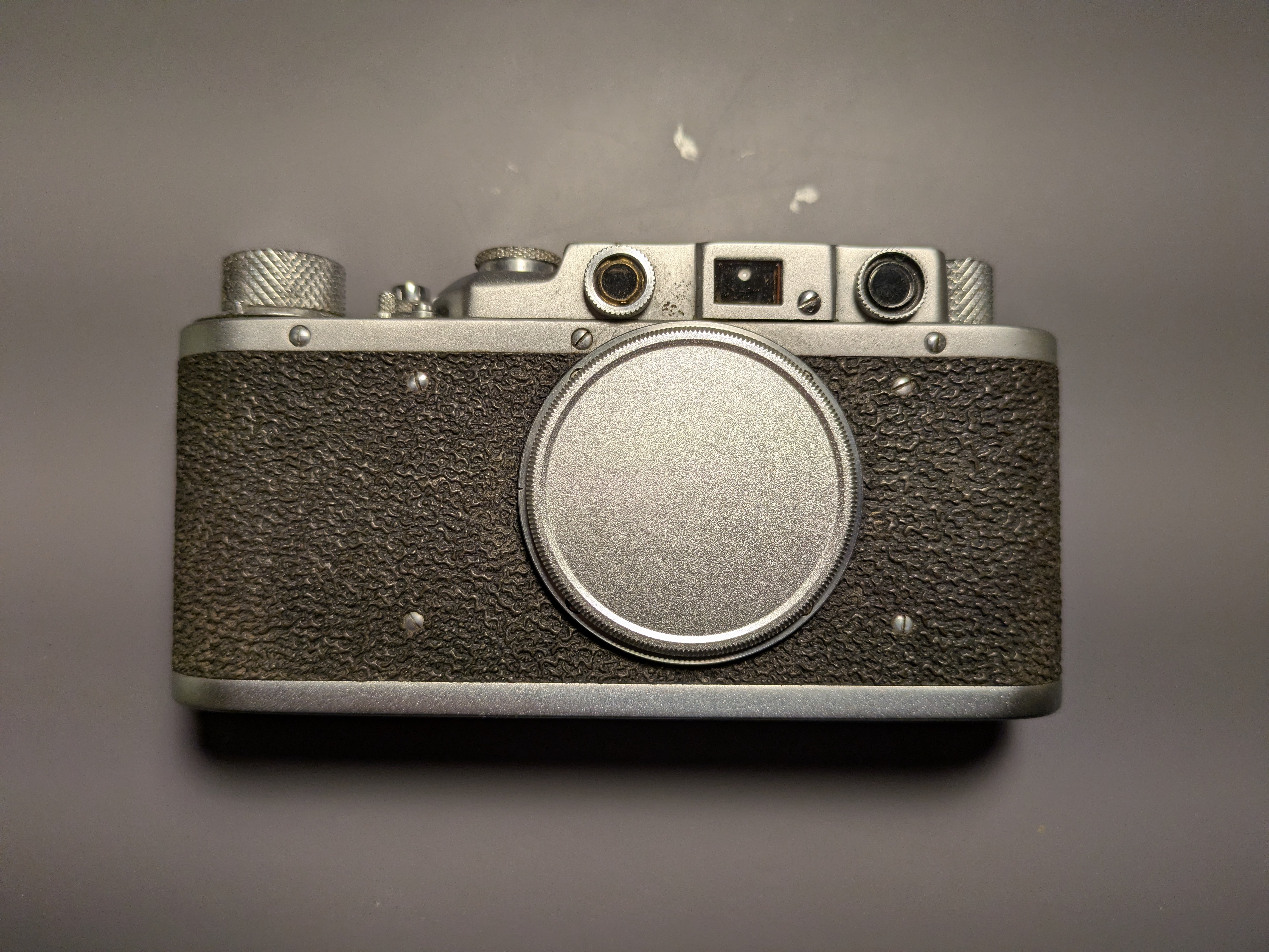
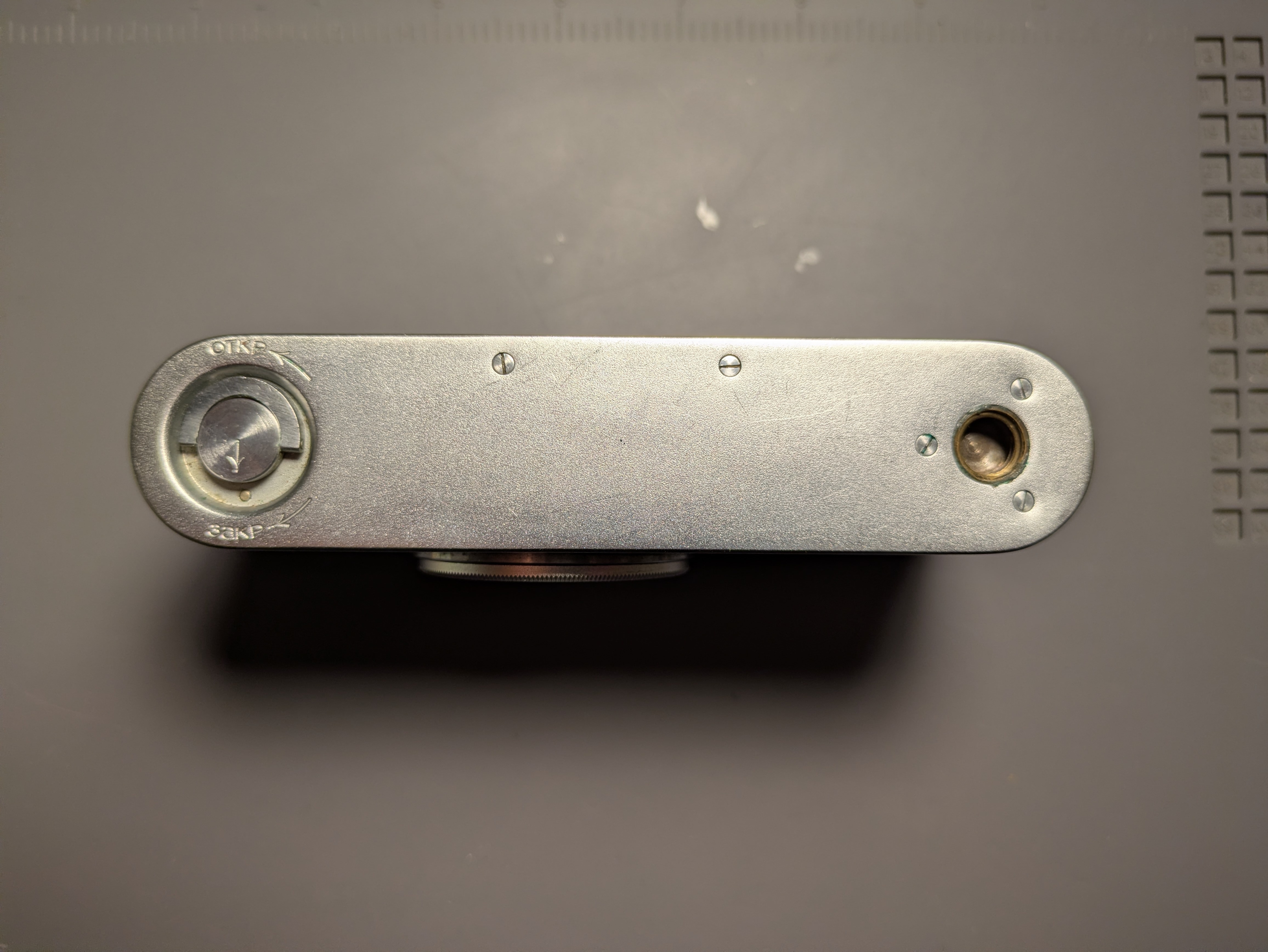
Here are a few shots of the overal appearance of the camera before I started disassembly.

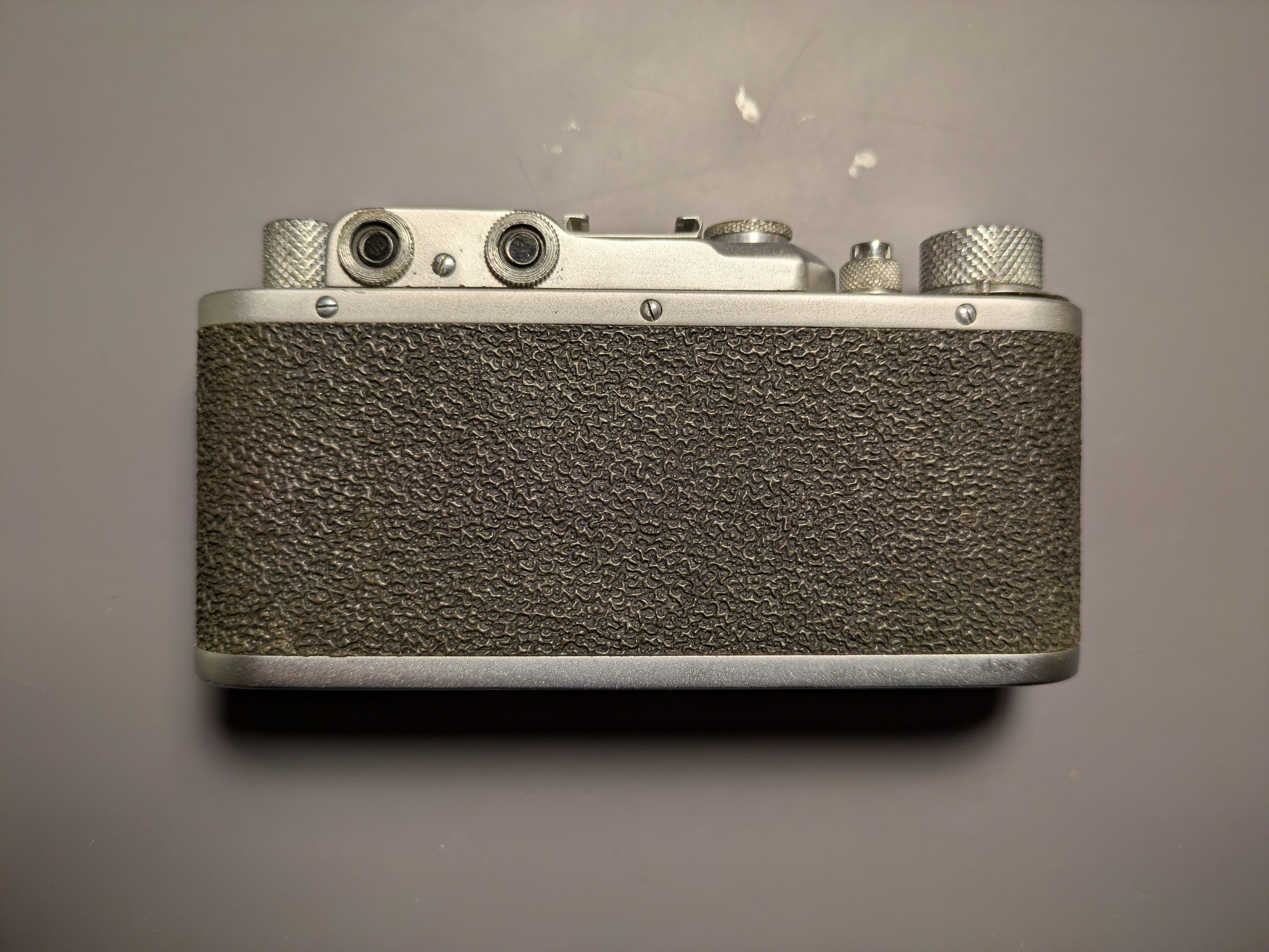
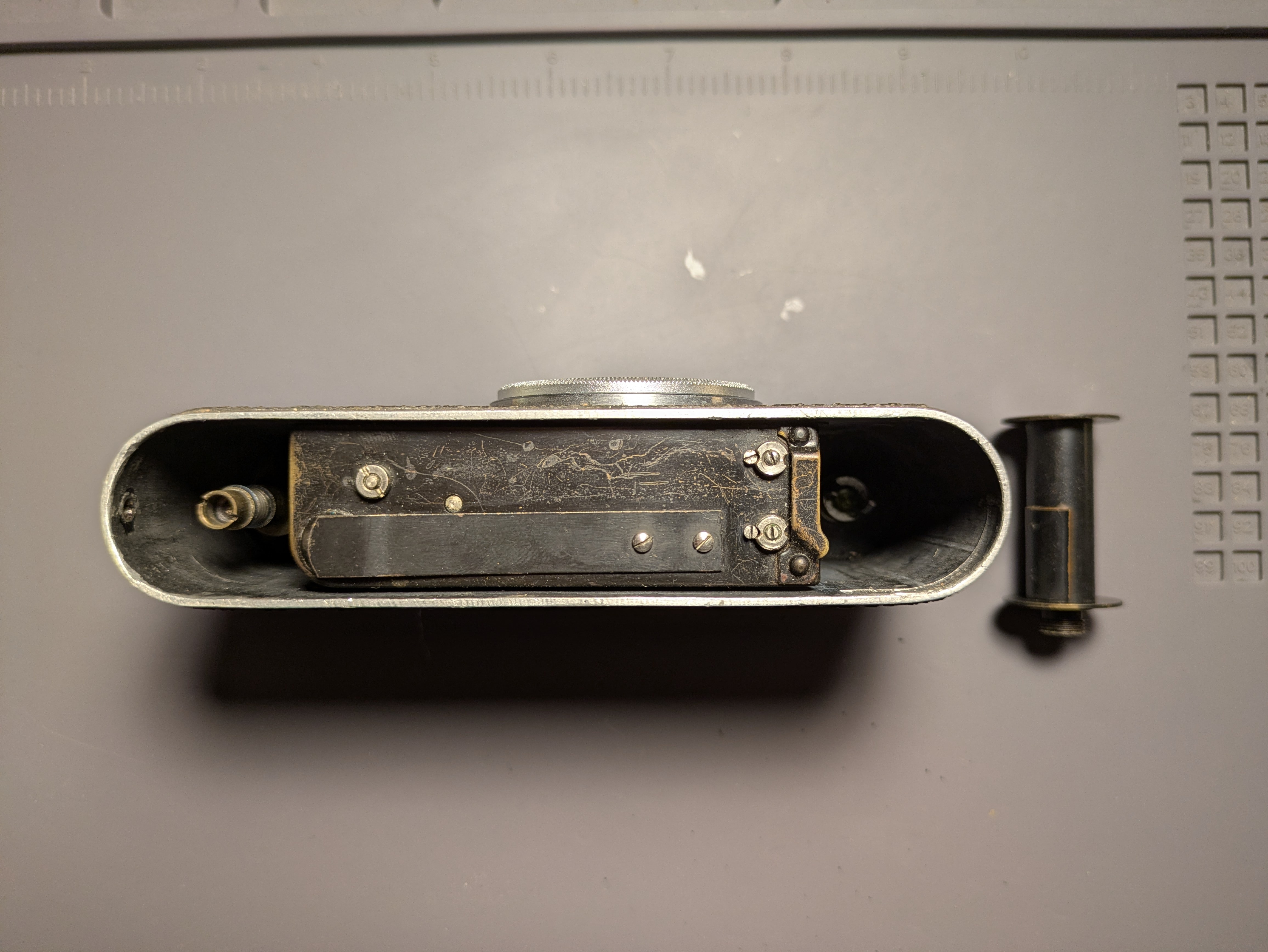
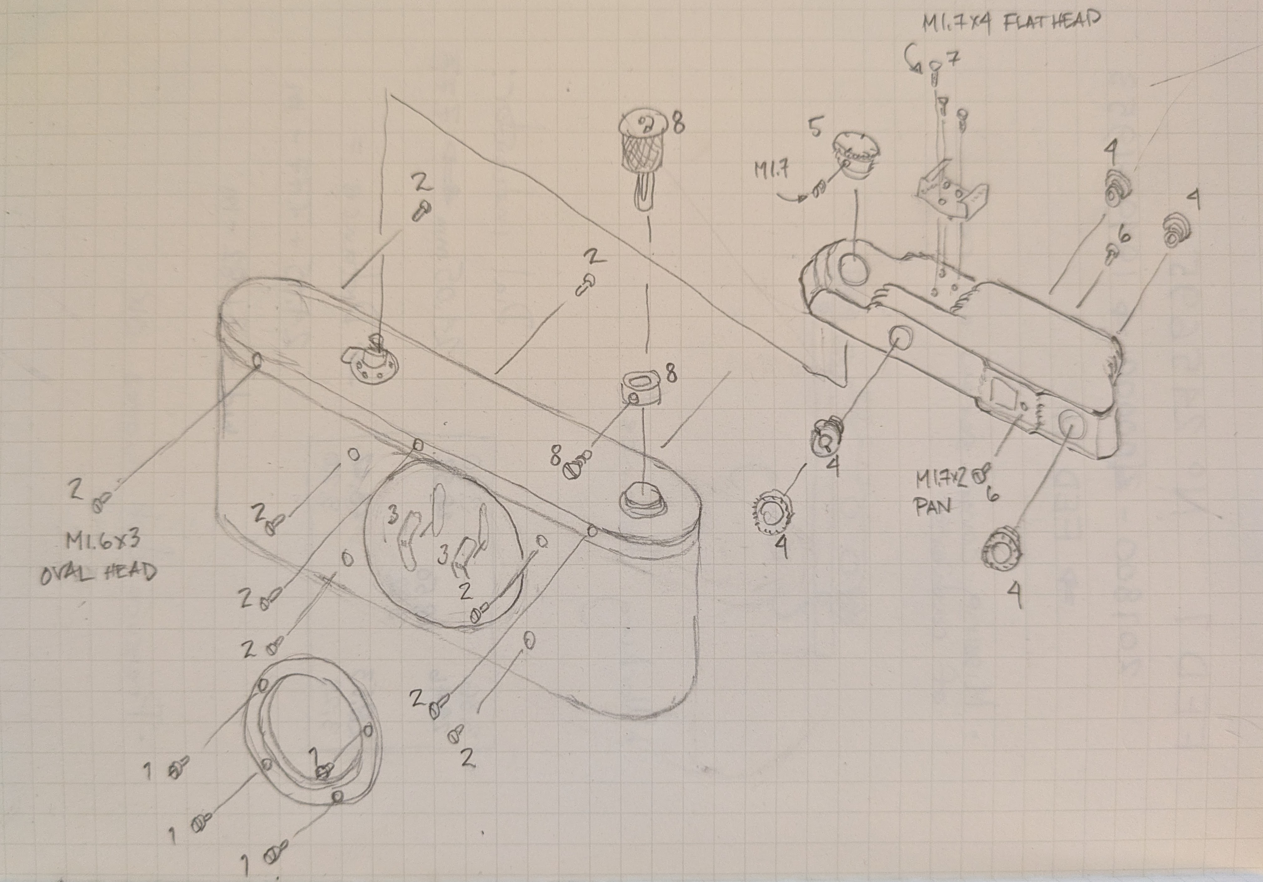
All in all looks to be in good condition and a good candidate for a rebuild. Let's start taking it apart, I'll use an exploded diagram I drew during my last (and first!) disassembly of a FED 1. There may some slight differences in the construction of this one, I've noticed online that there were small changes made to the design over the years and previous repairs to these may have lost or added washers, etc.
Disassembly
In the descriptions below, I will try to use a nomenclature for part names that is as consistent as possible with Maizenberg. Many of the images are small galleries; mouse clicks (shift-clicks) will move you forward (backward) through the galleries, or arrow keys should work if the gallery is in focus.
Removing the body
Remove the four screws holding the objective mount onto the body. These screws do not thread into the body, but rather into 2backing plates on the inside of the body. The plates will fall into the body and can be removed carefully. The upper backing plate might tangle with the rangefinder lever; be careful not to bend anything. Notice that the upper plate is different and has some notching along its top side. When removing the objective mount, be careful of any paper shims between it and the body. Keep track of their orientation and order.
Next, remove the 6 scews holdiong the body to the mounting cover and the 4 screws on the body front face. The body should now be loose and can be removed by gently pressing on the shutter body from below, making sure that the rangefinder lever is slightly pushed in so that it does not catch on the body. At this point the pressure disk, which holds the film against the film rails on the back of the shutter body will be loose and can be removed. Here was my first clear indication that the camera had been apart before: the 2 small leaf springs that keep the pressure disk pushing against the film were missing. I will either need to manufacture these or source them from a parts camera.
Removing the upper shield
To remove the the upper shield from the mounting cover, you need to remove the clamp for accessories (held on by three screws). The interval knob, which sets the shutter speed, is held by one or two setscrews (one in my case). Once this setscrew is loosened (there is no need to remove it), the interval knob may be unscrewed counterclockwise. Removing the viewfinder ocular, rangefinder oculars, and the wedge requires care to avoid damaging them. I used a ring wrench that I 3d printed (FreeCAD and stl files) to remove these safely. Finally, remove the two screws holding the cover, one front and one back. The upper shield can now be removed.
Removing the film return mechanism
The film return mechanism can be removed by lifting the film return knob to expose the screw in the ring. This will release the knob above and the driver below. Note the positions of the washer and spring.
Removing the shutter body
Remove the screw that holds the spring holding down the brake latch and remove the latch. Remove the screw (and spring) holding the exposure lever in place and remove the lever. The exposure disk now can be taken off by removing the setscrew that goes all the way through the drum axle (and thus must be removed completely).
Next, remove the shutter body. It is held on by three small screws into the mounting cover. If you look closely at the ribbon path on the second curtain sleeve, it looks like the spring was tensioned backwards. I've only seen a few FED 1 cameras opened up, but I've never seen the ribbons wound this way. Everything I have seen winds the two sleeves the same way.
Removing the cranking mechanism
Loosen the setscrew in the cranking knob and unscrew the knob. Don't rely on the brake spring to prevent the rotation of the drum when unscrewing the knob; hold it tightly with your left hand to avoid damaging the spring. Take off the frame counter dial and the spacer. This will reveal two screws that clamp the brake spring to the mounting cover. Remove these and you can remove a small bar from the underside of the mounting cover to release the brake spring. You can now remove the entire cranking mechanism from the bottom.
To disassemble the cranking mechanism, gently remove the brake spring being careful not to distort it. The brake ring is then free to come off. This spacer ring has a notch to allow the "s" shaped hook to protrude, make sure this is installed facing upwards when reassembling. You can unscrew the slotted "nut" at the bottom of the mechanism to disassemble completely. A washer, spring, washer, and the drum will then slide off the axle.
Removing the shutter release and drive drum
Removing the pressout gear
Testing rangefinder lever alignment
Removing rangefinder
Replacing the rangefinder beam splitter